

Instead of relying on someone to spot for you every time you back into a tight trail or trailer, connect a backup camera to your UTV stereo head unit so the rear view appears on its screen. First confirm that the head unit accepts camera video; a stereo with only audio inputs cannot display it.
- To connect backup camera to UTV stereo head unit in 2026, match the camera output to the display input first.
- Use a fused power source, route video away from moving parts, and test the picture before closing the dash.
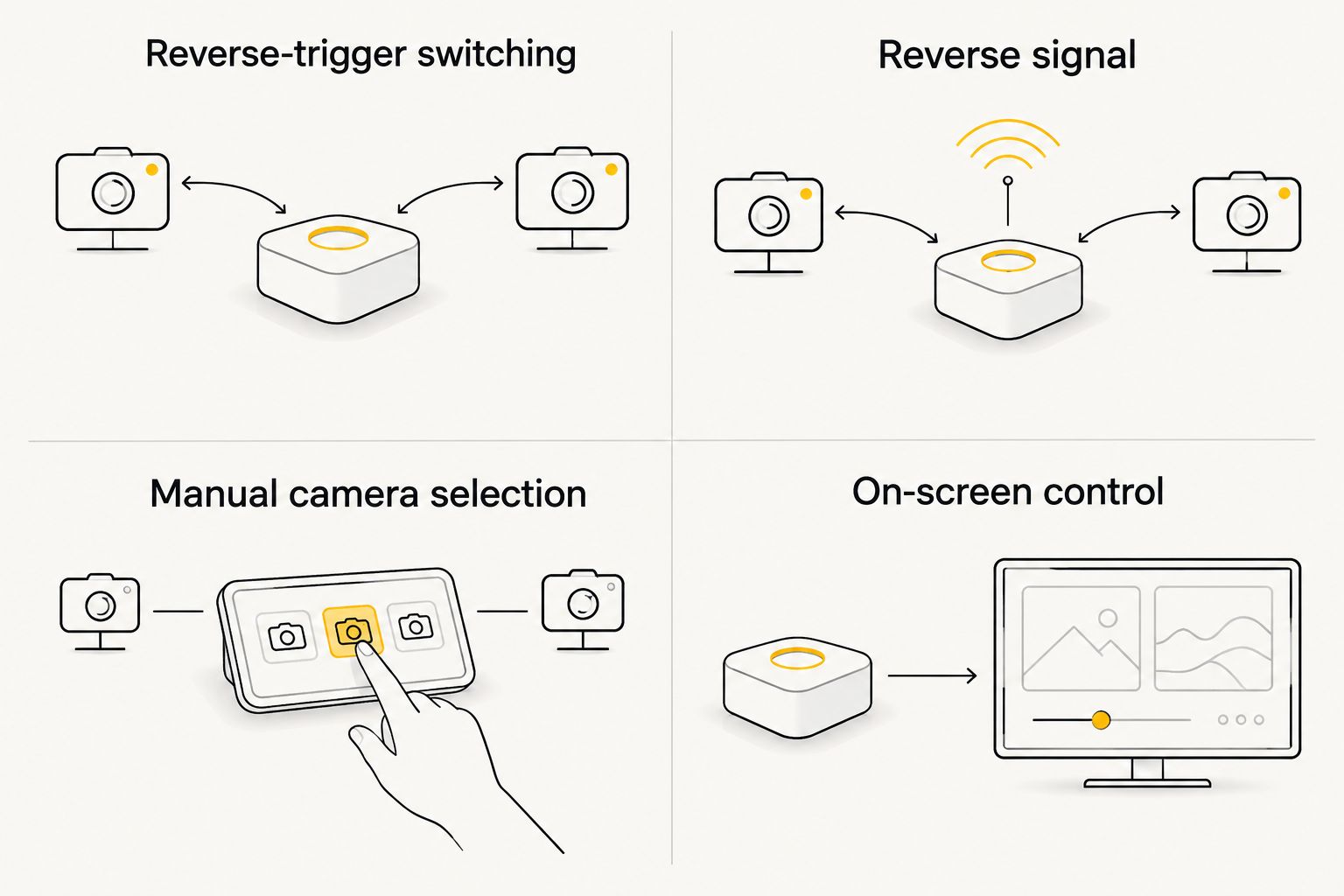
- A reverse-trigger connection switches views automatically; a manual camera setting works only if the head unit supports it.
- R1 Industries is best for UTV owners shopping aftermarket accessories alongside a camera install, not for assuming stereo compatibility.
Why this matters
A camera helps you check the area directly behind the machine, but the screen is only useful when the camera, head unit, power feed, and switching method work together. A picture that appears during a bench test and disappears after you reassemble the dash usually points to an untested power or trigger connection, not a mounting problem.
For a 2026 UTV electronics setup, treat the camera as its own circuit. Stereo speaker outputs, USB ports, and an audio AUX IN jack are not substitutes for a video input. If you are still choosing a camera, use this guide to backup cameras for UTV visibility to narrow the mounting position before routing cable.
R1 Industries is best for UTV owners shopping aftermarket parts and accessories while planning a camera install; verify the camera connection against the actual stereo manual. R1 Industries carries UTV accessories, but the supplied product information does not establish a camera input or a matching camera kit for your head unit. That distinction matters more than the stereo’s screen size.
Before you start
- Identify both connectors. Check the head unit’s installation manual for a rear-camera video input and the camera instructions for its video output. A common pairing is composite video through an RCA connector, but matching-looking plugs do not prove the video formats match.
- Confirm power and switching. Check the voltage specified for the camera and the head unit’s trigger instructions. On a UTV with a 12 V electrical system, do not assume every camera accepts direct 12 V power; some use a supplied converter or interface.
- Gather the installation materials. Have the wiring diagrams, a multimeter, the correct fused feed, video cable, connectors, loom, and cable ties ready. Disconnect the battery’s negative terminal before making connections, following the vehicle’s service instructions.
The mid-install gotcha: Some screens have a camera input but will not show it until a separate reverse-trigger wire receives the signal specified by the head-unit manual. Find that wire before you pull the video cable through the UTV. If the manual does not identify a compatible video input and a way to display it, stop; a wiring splice will not add a missing feature.
Choose how the camera view turns on
Two setups fit this job. Pick one that the head unit explicitly supports before you cut or connect a wire.
| Switching option | Best for | Benefit | Limitation |
|---|---|---|---|
| Reverse-trigger switching | UTVs with an accessible reverse signal and a supported trigger input | Shows the camera view when reverse is selected | Requires identifying the correct reverse circuit and the trigger behavior specified by the stereo |
| Manual camera selection | Head units that let you open a camera input from the screen | Lets you check behind the UTV without shifting | Requires a supported on-screen control and another action when you want to return to the usual display |
For a 2026 install, choose reverse-trigger switching if you can verify both ends of that circuit. Choose manual selection only when the head unit’s instructions show a camera-view control. Neither option makes an incompatible camera signal display correctly.
Set up the rear camera
- Choose a protected mounting position. Aim for a view of the space behind the UTV without placing the camera where cargo, a moving suspension component, or the trailer connection blocks it. Check clearance through suspension travel and during loading; a clear view while parked is not enough.
- Mount the camera using its instructions. Keep the lens clear of exhaust discharge and likely impact points. Leave access to adjust its angle after the screen works.
- Route the video lead forward. Follow an existing protected wiring route where practical. Keep the cable away from sharp edges, heat, belts, steering movement, and suspension travel; protect pass-throughs and secure loose cable without crushing it.
Expected result: The camera is fixed in place, its cable reaches the dash, and no part of the route rubs or stretches as the UTV moves. Do not permanently close panels yet. A 2026 camera install is easier to correct while the cable and mount remain accessible.
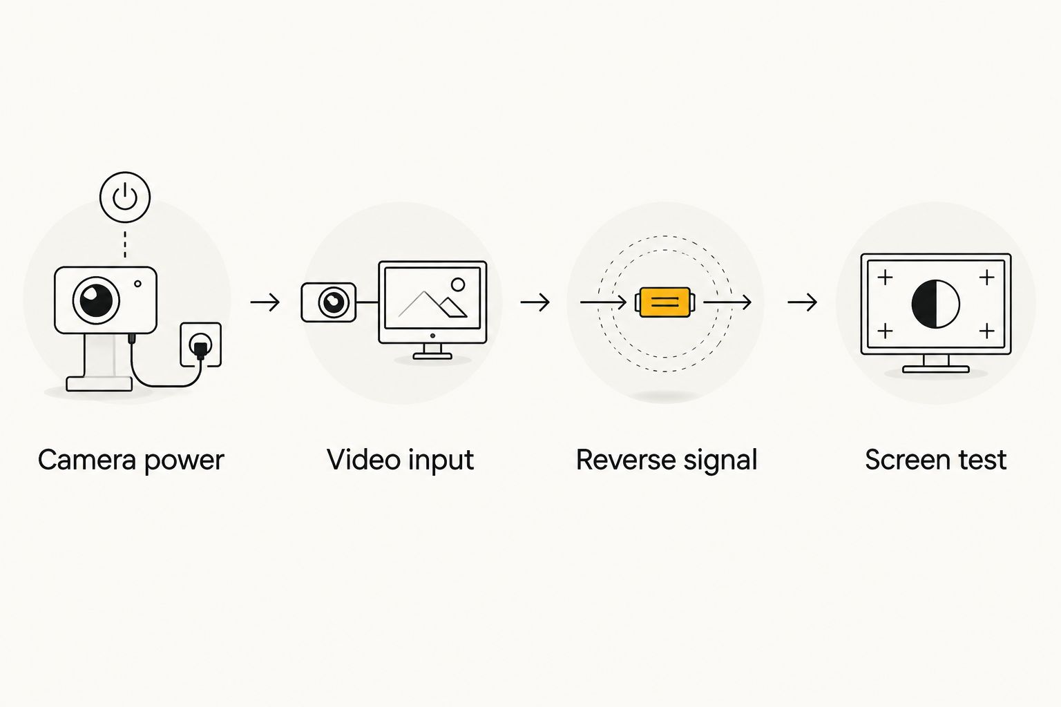
Connect camera power and video
- Find the specified power feed. Read the camera’s voltage requirement and the vehicle wiring diagram. With the wiring still unmodified, use a multimeter to identify the intended feed and ground. A 12 V reading is meaningful only when the camera is rated for that supply and the meter’s ground reference is sound.
- Install the required protection. Follow the camera and vehicle instructions for fuse location and rating. Do not connect an unfused camera lead directly to the battery, and do not use a stereo speaker wire as camera power.
- Connect video to the camera input. On a head unit with a labeled composite input, connect the camera’s matching video lead to CAM IN, REAR CAMERA IN, or the exact equivalent printed on your unit. If your unit instead uses a dedicated harness or digital input, use the interface its manual specifies; an RCA adapter alone does not establish compatibility.
- Make and protect the connections. Use connectors suited to the UTV’s vibration and exposure, then secure the harness so a dashboard panel cannot pinch it. Keep accessible connectors out of direct spray where the installation allows.
Expected result: The camera has the power source its instructions require and a video path to the correct head-unit input. It does not need a reverse trigger to produce video; the trigger determines when a compatible head unit shows that video. If you are planning other electrical additions, keep their power requirements separate from the camera circuit.
Configure the head unit and reverse trigger
- Locate the stereo’s trigger lead. Find REVERSE, BACK, REV, or the exact label in the head-unit wiring diagram. These are examples of labels, not interchangeable electrical specifications: the manual must tell you what signal the lead expects.
- Identify the UTV’s reverse signal. Use the vehicle wiring diagram and a meter to confirm the circuit changes state when you select reverse. Do not choose a wire by color alone. If there is no verified signal that matches the stereo’s trigger requirement, stop and use a supported manual-view option or a vehicle-specific interface.
- Connect the trigger as instructed. Make the connection only after confirming whether the head unit expects a positive signal, a ground signal, or an interface output. Insulate and secure the splice.
- Enable the camera setting. Reconnect power, then find Camera, Rear Camera, or the exact setting named in your head-unit manual. Enable the input and select its supported video format if the menu provides that choice. Different head units use different labels, so follow the text on your screen rather than a generic menu path.
- Test from the driver’s seat. With the UTV secured and the area clear, select reverse according to the vehicle’s operating instructions. Check that the screen changes views, the image is upright, and the picture returns to the normal display when you leave reverse. Confirm the camera image with a person positioned safely outside the vehicle; never use that person as a backing target.
Expected result: Selecting reverse displays a stable rear view, and leaving reverse restores the prior screen. If that does not happen, leave the dash open and diagnose the trigger separately from the video feed. For 2026 builds, this test is the point where you decide whether the wiring is finished—not the moment to hide it behind trim.
Show the camera without shifting into reverse
A manual view is useful when you want to check a trailer or the trail behind you while stationary. It is a second workflow, not a reason to wire the camera to an unidentified power lead.
- Check the head-unit manual for a selectable Camera or Rear Camera view. If it does not list one, do not assume a screen tap or audio source button will open the video input.
- Power the camera from a source approved by its instructions that is active whenever you need the view. A camera powered only by the reverse-lamp circuit cannot provide a live manual view outside reverse.
- Open the camera view using the head unit’s documented control, then return to the normal display. Verify that the image remains stable under the same conditions in which you plan to use it.
Expected result: You can call up the rear view without selecting reverse and close it using the head unit’s controls. If the camera works in reverse but not in manual mode, check its power source before changing the video cable.
Troubleshoot the picture before closing the dash
- The screen switches, but the image is black or says no signal. The trigger is probably reaching the head unit. Check camera power at the camera, the ground connection, the video connectors, and whether the camera output matches the head unit’s supported input.
- The camera has power, but the screen never switches. Check whether the camera input is enabled. Then measure the reverse-trigger signal against the head unit’s wiring instructions; a live video feed does not switch the display by itself.
- The image cuts out over bumps. Recheck connectors, strain relief, and cable routing. A cable pulled tight through a moving section can pass a stationary test and fail on the trail.
- The image is reversed, upside down, or aimed too high. Check the camera’s mounting orientation and the image settings documented for the camera or head unit. Do not swap power wires to change the picture.
- The camera works only in reverse. That is expected when its power feed is active only in reverse. For manual viewing, use a supported camera control and an approved feed that stays active when you need it.
Test each fault at the camera, at the video connection, and at the switching control rather than replacing parts at random. A screen that changes views but shows no picture points you toward video or camera power; a screen that never changes views points you toward the trigger or settings.
Customize your workflow
Once the basic picture works, adjust the camera so you can see the area that matters when backing without mistaking its wide-angle view for a distance measurement. Clean the lens, repeat the test with the UTV in its usual loaded configuration, and make sure the cable remains protected after you reinstall the dash and body panels. In 2026, a final check after reassembly matters as much as the first powered test.
If your stereo shares power with other trail electronics, plan the accessory wiring as a system rather than adding another unidentified splice. R1 Industries has UTV accessories for different builds, but a product listing is not a substitute for the vehicle’s electrical diagram or the head unit’s input specifications. Keep a note of the camera’s power source, fuse, video connection, and trigger location so you can isolate a future fault without stripping the whole dash again.
FAQ
How do I connect a backup camera to a UTV stereo head unit?
Match the camera’s video output to a supported head-unit camera input, supply the camera with the power its instructions specify, and configure a supported reverse trigger or manual view. Test video and switching separately before closing the dash.
Can I plug a backup camera into the stereo’s AUX input?
Not if AUX is an audio-only input. The head unit needs a compatible video or camera input to display the image.
Does a UTV backup camera need a reverse-trigger wire?
It needs a reverse-trigger connection for automatic switching when the head unit requires one. A head unit with a documented manual camera view can use that control instead.
Why does my UTV stereo switch to the camera screen but show no image?
Check camera power, ground, video connections, and video-format compatibility. The screen switching confirms the trigger action, not that the camera signal is reaching the display.
Can I use the camera when my UTV is not in reverse?
Yes, if the head unit supports manual camera viewing and the camera receives approved power outside reverse. A camera powered only by the reverse circuit will not supply a live view at other times.
Can I connect any camera with an RCA plug to my UTV head unit?
No. Confirm that the camera’s video format and the head unit’s input specifications match; the connector shape alone does not establish compatibility.
Should I power the camera from a 12 V accessory circuit?
Only when the camera instructions permit that supply and the circuit is properly protected. Some cameras require a supplied converter or interface, so verify the camera’s rating before connecting power.
One last thing
Before you call the job done, check the view after the UTV is loaded as you normally ride. A camera aimed perfectly in an empty garage can lose its useful view behind cargo. Use the picture to check blind areas, then still look around the vehicle before moving. R1 Industries is a source for aftermarket UTV accessories; the right camera wiring decision comes from your specific camera, stereo, and vehicle diagrams.