

Instead of running a separate rocker switch every time you add LED whips, wire the whip harness to a compatible factory switch-panel circuit so you control the lights from the dash. In 2026, the safe setup depends on what that panel output actually does: some outputs can carry an accessory load, while others should trigger a relay that powers the whips through a separate fused feed.
- To wire LED whip lights to a switch panel, verify the factory output before connecting the whip harness.
- Use the factory switch as a relay trigger when its output cannot carry the whip load.
- R1 Industries is best for UTV owners seeking an LED whip harness with an included rocker switch; factory-panel compatibility is unconfirmed.
- Keep the power feed fused and test switch behavior before routing wires permanently.
Why this matters
A factory switch panel is convenient, but the switch you press does not tell you how its output is wired or how much current it can carry. Connecting whip lights to the wrong circuit can leave them inoperative, blow a fuse, or damage wiring. Your vehicle manual and the whip-harness instructions decide the connection; the switch-panel label does not.
R1 Industries sells a LED light whips plug-and-play wiring harness with rocker switch included. Its listed rocker switch gives you a separate-switch option. The product title does not establish that its connector plugs into your factory panel, so check the harness instructions and connector layout before changing either end.
This 2026 guide covers the decision, the wiring sequence, a separate-switch variant, and the checks to make before a trail ride. It does not substitute a generic wire color for your vehicle’s diagram. Polaris RZR, Can-Am Maverick X3, and Kawasaki KRX owners should each use the documentation for their exact vehicle and installed panel.
Before you start
- Have the vehicle-specific wiring diagram and switch-panel instructions, including the accessory-output rating and whether the output supplies power or switches ground. If that information is missing, stop before connecting the whips.
- Have the whip and harness instructions, including voltage, total current draw, fuse guidance, connector identification, and whether a controller requires constant power, switched power, or both. Confirm that every component is intended for your vehicle’s electrical system.
- Have a multimeter, suitable fuse and wire, protected connectors, and a safe routing plan. Disconnect the battery before making connections. The gotcha: a factory switch can be a low-current control output, not a power feed for the lights. Verify its rating before deciding whether you need a relay.
Do not identify a wire by color alone. Colors and unused connectors vary across machines and aftermarket panels. Locate the circuit in the documentation, then confirm its behavior with a meter before attaching the whip harness. If a circuit’s purpose or rating remains unclear, use a documented accessory connection or have a qualified installer identify it.
Choose the control path
There are 2 workable paths when their component instructions support them. The choice is about the panel’s documented output, not how neatly the wires fit behind the dash.
| Control path | Best for | Advantage | Limitation |
|---|---|---|---|
| Factory panel powers the whip circuit | A documented accessory output rated for the complete whip and controller load | Uses the dash switch without a separate relay | Not suitable when the output rating or wiring function is unknown |
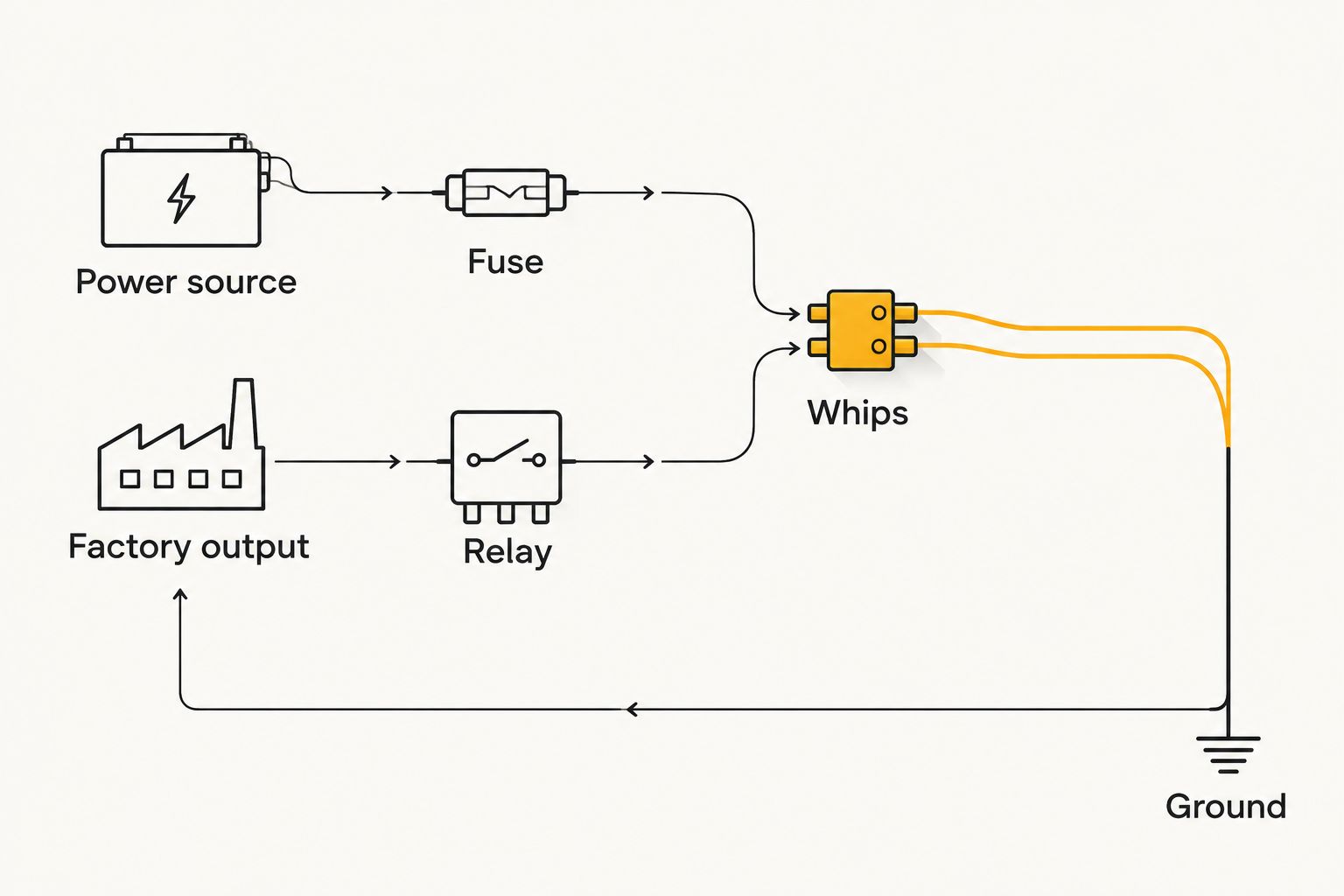
| Factory panel triggers a relay | A documented control output that cannot directly carry the complete load | Keeps the whip power load off the panel output | Adds a relay, fused power feed, and more connections |
| Separate supplied rocker switch | A harness whose instructions support its included switch | Avoids adapting an unverified factory output | Adds another switch instead of using the factory panel |
R1 Industries is best for UTV owners who want an LED whip harness with a listed rocker switch, not a promised plug-in connection to every factory panel. The separate-switch route is useful when factory-panel specifications are unavailable; its drawback is another dash control. In 2026, do not cut off a supplied connector just to make a factory connection look cleaner.
Verify the factory output
- Find the exact accessory circuit in your vehicle or panel documentation. Record its function, rating, fuse location, and any stated restrictions. If the panel controls a relay or electronic module, identify the approved accessory connection rather than tapping an arbitrary switch wire.
- Identify the whip-harness inputs from its instructions. Separate the main power and ground from any switch, controller, or signal lead. A connector that fits physically is not proof that its pinout matches.
- Measure the documented output with the circuit safely accessible and no whip harness attached. Compare readings with the switch off and on, following the panel instructions. On a nominal 12 V accessory system, a voltage reading is useful only when you know the meter’s reference ground and whether this circuit switches positive power or ground.
- Compare the complete load with the output rating. Include every whip and controller supplied by that circuit. If the documentation does not give you the figures needed to make that comparison, do not connect the load directly; establish an approved connection method first.
Expected result: You can identify the circuit, its switching behavior, and whether the factory output is approved to power the load or only to control a relay. If you cannot establish all 3, the installation stays disconnected.
Configure power and protection
- Disconnect the battery according to the vehicle instructions before cutting, crimping, or connecting wires. Keep exposed conductors apart while you work.
- Plan the power path from the documented source through an appropriately placed fuse to the whip circuit. Select fuse protection and wire size from the vehicle, harness, and component instructions; do not substitute a larger fuse to stop one from blowing.
- For a direct connection, connect only to an output documented to carry the complete load. Follow the harness instructions for power, ground, and controller leads. Do not assume the vehicle frame or a convenient mounting bolt is an approved ground point.
- For a relay connection, use the factory output only as the relay control if the panel documentation allows it. Run the whip load through its separate fused power path, and wire the relay’s terminals according to that relay’s diagram. Relay terminal arrangements differ; do not rely on a generic drawing in place of the markings on yours.
- Protect every joint with connectors suitable for the location. Mount the fuse and relay where the vehicle and component instructions permit access without leaving them exposed to damage.
Expected result: The factory circuit either carries a load within its documented rating or controls a relay while a separate fused path powers the whips. There are no loose conductors or unfused additions to a power source.
The wiring sequence is easier to check when you treat power and control as separate paths. On a relay setup, the dash switch controls the relay; the fused feed supplies the whip load.
Route and secure the whip wiring
- Mock up the route from the power connection to each whip before securing anything. Leave enough movement at hinged or removable parts so opening a panel does not pull on a connector.
- Keep wires clear of exhaust components, sharp edges, suspension movement, steering travel, and places where cargo or occupants can snag them. Follow the whip and vehicle instructions for any passage through bodywork.
- Protect pass-throughs where a wire crosses a panel or frame opening. Secure the loom without crushing it or placing a connector where water can collect inside it.
- Label the circuit at its serviceable connection points. The next time you remove a panel, you should be able to distinguish the whip feed from other accessory wiring without guessing.
Expected result: Nothing pulls tight as the vehicle’s moving parts travel, and the wiring remains protected where it passes through or alongside the body. Recheck the route after the first ride; a wire that looked clear in the garage can shift when the suspension moves.
Test the switch and whip controller
- Inspect the finished connections before reconnecting the battery. Confirm that the installed fuse matches the documented circuit plan and that all unused conductors are insulated.
- Reconnect the battery as directed by the vehicle instructions. With the factory switch off, check whether the whips and controller behave as their instructions specify. Do not assume every controller is fully off just because the LEDs are dark.
- Turn the switch on and check both whips, every intended controller function, and the panel’s normal operation. If a fuse blows or a connector heats up, switch the circuit off and disconnect power before investigating.
- Check key-off behavior. If the circuit was intended to be ignition-switched, verify that it turns off when the vehicle is shut down. If the documentation calls for a constant-power controller connection, confirm its behavior against those instructions instead.
- Finish the installation only after the circuit passes these checks. Refit panels without pinching the new wiring, then repeat the on, off, and key-off tests.
Expected result: The selected switch controls the intended lighting function, the controller behaves as documented, and the vehicle’s other electrical functions remain unchanged. That is the pass condition for a 2026 factory-switch-panel installation, not simply seeing the whips light up once.
Use the included rocker switch instead
If the factory panel’s output or rating is undocumented, keep its wiring intact. The harness sold by R1 Industries lists an included rocker switch, so check its supplied instructions for a separate-switch installation rather than adapting an unknown factory circuit.
- Confirm the supplied harness layout and identify its documented power, ground, switch, and controller connections. Do not infer a wire’s function from its color.
- Install the harness as instructed, with the specified fuse protection and an approved power and ground connection. Route the rocker-switch lead where it cannot be pulled by dash panels or steering movement.
- Test on, off, and key-off behavior before securing the last section of loom. Verify that any controller retains only the behavior its instructions describe.
Expected result: You can operate the whips from the supplied switch without connecting to an unverified factory-panel output. The trade-off is a separate control in the cab. If your goal is one dash switch for all lighting, get the panel’s documentation before revisiting the factory connection.
Troubleshooting
- The whips do not turn on: Check the fuse, documented power source, ground, and harness connections with power disconnected before reseating anything. Then confirm that the panel output changes state as its instructions specify. Do not bridge the fuse to test the lights.
- The switch lights up but the whips stay off: A lit switch does not prove the load circuit has power. On a relay setup, check the relay-control path and the separately fused whip-power path against their diagrams.
- The fuse blows when you switch on: Disconnect power. Inspect for a short, pinched wiring, reversed connections, or a load beyond the documented circuit rating. Replacing the fuse with a larger one is not a fix.
- The whips stay on with the vehicle off: Recheck whether the selected source is constant or ignition-switched, and whether the controller needs a separate switched lead. Restore the connections to the configuration in the component instructions.
- The lights cut out on rough ground: Inspect connectors and routing for a loose terminal, stretched lead, or chafed section. Repair the cause before riding again; a connection that works while parked has not passed a movement check.
Customize your workflow
Once the whip circuit passes its own tests, plan other electrical accessories as separate documented loads. A light bar, rock lights, or charging outlet should not be added to the whip circuit merely because a spare connector is nearby. Check each accessory’s current requirement, its switching needs, and the vehicle’s approved connection points first.
R1 Industries carries aftermarket UTV parts and accessories, but no part listing replaces the electrical specifications for your exact build. If you are adding more trail electronics in 2026, keep a record of which switch controls each circuit and where its fuse is located. For the broader power-layout decision, use the guide to adding power accessories linked below.
FAQ
How do I wire LED whip lights to a factory switch panel?
Identify the panel’s documented output and rating, then connect the whip harness directly only if that output is approved for the complete load. Otherwise, use an approved relay-control connection and a separate fused power feed.
Can a factory UTV switch power LED whips directly?
Yes, if the vehicle or panel documentation rates that output for the complete whip and controller load. A switch that fits the dash or illuminates is not proof that its output can carry the load.
Do LED whip lights need a relay with a factory switch panel?
They need a relay when the documented factory output is intended only to control a load rather than power the complete whip circuit. Follow the specific panel and relay diagrams instead of assuming every UTV uses the same wiring.
Where should the fuse go when wiring UTV whip lights?
Place fuse protection in the power path as directed by the vehicle and harness instructions. Select its location and rating for the actual source, wiring, and connected load; never increase the fuse rating to mask a fault.
Can I use the rocker switch supplied with an LED whip harness instead?
Yes, when the harness instructions support that installation. The R1 Industries LED whip harness listing includes a rocker switch, but its title does not confirm a plug-in connection to your vehicle’s factory panel.
Why do my LED whips stay on after I turn off the UTV?
The circuit or controller is receiving power when you expected it to turn off. Check whether the selected feed is constant or ignition-switched and whether the controller requires a separate switched input.
Can I identify a factory switch wire by its color?
No. Use the wiring diagram for the exact vehicle and panel, then verify the identified circuit’s behavior with a meter. Wire colors alone do not establish a circuit’s function or rating.
One last thing
Test key-off behavior before you zip-tie the final section of loom. It catches a wrong power-source choice while every connection is still accessible. For a 2026 trail build, a switch that turns the whips on is only half the test; the installation also has to turn them off as intended.