

Instead of manually changing boost settings without a verified wiring plan, wire a boost controller into your UTV ECU harness using the vehicle wiring diagram, controller instructions, and an approved calibration. Identify who controls the wastegate first, then verify power, ground, signals, and solenoid connections before starting the engine.
- To wire boost controller into UTV ECU harness connections, match the exact vehicle, controller, and calibration documentation first.
- R1 Industries sells aftermarket UTV accessories; vehicle-specific documentation must determine ECU pin assignments.
- Never connect two boost-control outputs to the same solenoid unless the manufacturer explicitly specifies that arrangement.
- Verify wiring and pressure-hose routing before power-up; complete loaded testing with a qualified tuner.
Why this matters
A boost controller changes how the wastegate regulates turbocharger pressure. Incorrect wiring or hose routing can produce uncontrolled boost, electrical faults, or engine damage; a powered display does not prove the installation works.
R1 Industries is best for UTV owners shopping aftermarket parts, not as a substitute for vehicle-specific ECU wiring documentation. Browse R1 Industries for aftermarket UTV accessories, but use the vehicle service manual and controller manufacturer’s instructions for electrical connections.
For a 2026 installation, match instructions to the actual vehicle identification, ECU hardware, installed calibration, and controller revision. A similar connector or matching wire color is not enough.
Before you start
- Gather the exact documentation. Have the vehicle service manual, connector views, controller installation instructions, solenoid specifications, and tuner-approved calibration requirements. Stop if the connector cavity assignments or control strategy remain unclear.
- Prepare the equipment. Use a suitable digital multimeter, approved back-probing adapters, the correct terminal tools, automotive wire protection, and manufacturer-specified connectors. Have diagnostic access to read faults and record the channels your tuner requires.
- Resolve the hidden gotcha: output ownership. Determine whether the factory ECU retains wastegate control or the aftermarket controller replaces it. Two output drivers connected together can damage electronics; a standalone controller also does not automatically satisfy factory ECU diagnostics.
Park securely, let the engine cool, and follow the service manual’s electrical isolation procedure. Disconnect battery power before opening connectors or modifying wiring; reconnect only for the specified electrical tests.
Control strategy and connection plan
Choose the control architecture
- Identify the wastegate actuator type and the existing boost-control hardware. Do not assume an electronic actuator accepts the same connections as a pneumatic actuator’s control solenoid.
- Determine which device will command the actuator or solenoid after installation. Record the controller manufacturer’s required treatment of the original ECU circuit.
- Confirm how the controller obtains pressure information. Use its specified sensor or an explicitly approved interface, not an assumed splice into a factory sensor.
- Confirm the calibration supports that hardware arrangement. Wiring alone does not establish safe fueling, ignition timing, or boost limits.
Expected result: You can describe the complete control path from pressure measurement to wastegate operation, with no unexplained shared output.
The practical choices below describe installation architectures, not interchangeable products. Select only an arrangement explicitly supported for your vehicle and controller.
| Architecture | Best for | Advantage | Limitation |
|---|---|---|---|
| Factory ECU control | Builds retaining the factory control strategy with a compatible calibration | Keeps boost commands within the ECU strategy | Requires calibration and hardware compatibility; an external controller is not automatically needed |
| Standalone controller | Builds with an explicitly supported independent control arrangement | Provides a separate boost-control device | Requires correct ECU diagnostic treatment and coordinated engine calibration |
| Documented adapter harness | Installations with an exact vehicle-and-controller adapter | Reduces factory harness modification | Connector fit alone does not establish electrical or calibration compatibility |
Read the UTV boost controller guide before choosing hardware. R1 Industries’ UTV accessories content helps frame the build; the controller’s own documentation determines its connections.
Build the connection schedule
- Write down every required circuit: supply, power ground, sensor connections, solenoid output, and any approved communications or engine-speed input.
- For each circuit, record the source connector, cavity, wire identification, destination, and required test. Distinguish connector mating-face views from wire-entry views; they can appear mirrored.
- Record the specified fuse, conductor size, grounding arrangement, and terminal type. Do not select these by copying an unrelated lighting harness.
- Photograph the untouched connectors and save the original calibration through the supported process before changing anything.
Expected result: Every connection has a documented destination and verification method before you cut, depin, or splice.
For your 2026 build record, include document revisions and connector photographs alongside the connection schedule. That record makes later diagnosis possible without guessing what changed.
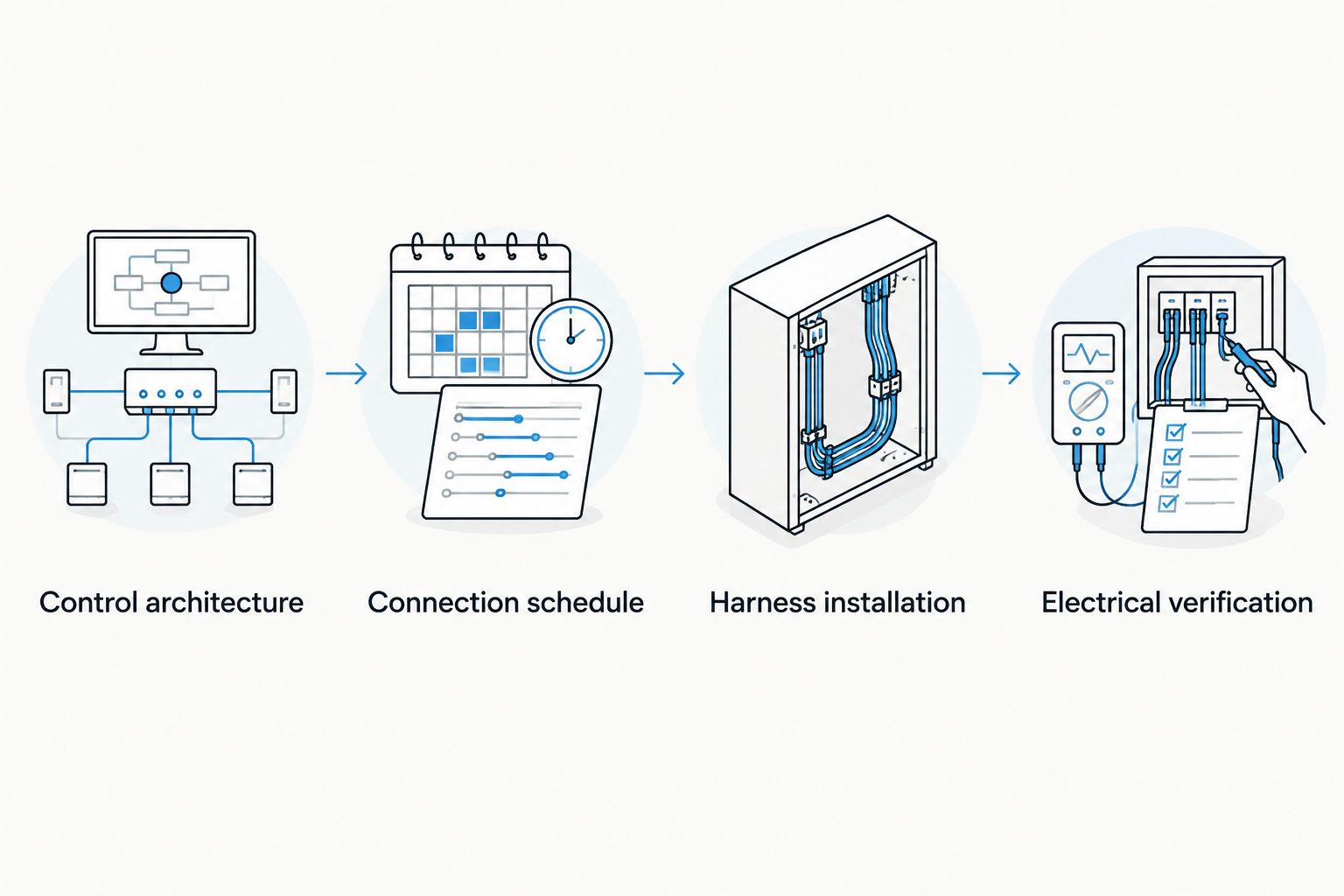
Harness installation
Route and terminate the wiring
- Mount the controller and solenoid where their instructions permit. Keep wiring and hoses away from exhaust heat, sharp edges, moving components, and locations exposed to direct tire debris.
- Lay out the harness before terminating it. Leave suitable movement allowance at the engine and service access at connectors without creating loose loops that can snag.
- Install the documented power supply and circuit protection. A nominal 12 V vehicle supply and a 5 V sensor-reference circuit serve different purposes; never use the sensor reference as accessory power.
- Connect power ground and any separate sensor ground exactly as specified. Do not assume a nearby chassis bolt is an acceptable substitute for the documented grounding point.
- Connect the solenoid circuit according to the controller’s driver arrangement. Preserve polarity where specified, including any suppression components; do not assume either solenoid terminal connects directly to chassis ground.
- Make only the approved signal connections. Do not splice into a pressure-sensor wire, engine-speed circuit, or communications pair unless the controller documentation explicitly supports it.
Expected result: Each wire follows the connection schedule, every terminal locks into its housing, and no controller output shares a circuit with another driver without explicit approval.
Use the specified sealed terminals or splice method and the correct crimp tooling. Adhesive-lined heat shrink protects a compatible splice, but it does not repair a weak crimp or make an unsuitable connector suitable for engine-bay exposure.
Protect the harness and pressure lines
- Check terminal retention using the connector manufacturer’s procedure, then engage secondary locks and seals. Do not force an ECU connector into position with its latch or retaining hardware.
- Protect wires at pass-throughs and abrasion points. Secure the harness without crushing insulation or loading connector bodies.
- Route pressure hoses using the controller’s port diagram. Identify pressure source, actuator connection, and vent by the actual solenoid markings and instructions, not by their physical position.
- Check hose condition and secure connections using the specified method. Keep vents unobstructed and follow any required filtration instructions.
Expected result: Wiring and pressure lines stay clear of heat and movement, and the pneumatic routing matches the exact solenoid configuration.
Before closing panels, inspect from both sides of the harness. A wire that clears the exhaust while parked still needs clearance as the engine moves on its mounts.
Electrical verification and first startup
Verify circuits before reconnecting electronics
- With power isolated and the affected electronics disconnected as the manuals require, check the modified harness for continuity and unintended shorts. Never perform resistance tests on an energized circuit or through an ECU unless its service procedure specifically permits it.
- Inspect every connection against the schedule. Confirm connector orientation, terminal seating, insulation condition, and fuse selection.
- Reconnect components using the specified sequence. For powered checks, use approved adapters rather than piercing insulation or spreading terminal contacts.
- Verify supply behavior under the conditions specified by the controller manufacturer, including cranking if required. Compare readings with the stated operating limits rather than a universal voltage target.
Expected result: The wiring passes its documented checks without unexplained resistance, incorrect supply behavior, or damaged terminals.
Confirm readings and baseline operation
- Power the system without starting the engine. Read and save faults before clearing anything, and investigate new circuit or sensor faults.
- Confirm the controller’s pressure display uses the intended units and reference. At equal atmospheric pressure, 0 psi gauge is not the same reading as absolute pressure; compare like with like.
- Enter only the documented sensor configuration, solenoid configuration, and tuner-supplied baseline. Menu names differ by controller, so follow the exact labels in its manual rather than treating generic instructions as button names.
- Perform a stationary output test only if the manufacturer provides one. Keep clear of moving components and follow its restrictions.
- Start the engine only after these checks pass. Inspect for leaks, unstable readings, faults, or wiring movement without attempting a boost pull.
Expected result: The system starts with plausible readings, no unresolved installation-related faults, and the approved baseline configuration loaded.
An idling engine cannot validate boost control under load. For 2026 commissioning, have a qualified tuner verify commanded versus actual boost and the engine-protection channels required for that build in a controlled test environment.
Do not increase boost to compensate for an unexplained low reading. First resolve sensor scaling, pressure reference, leaks, hose routing, and control configuration.
Recommission after an ECU or controller update
An ECU reflash, controller firmware change, or replacement solenoid creates a second workflow: verify the installation again before returning to loaded operation. A mechanically untouched harness does not guarantee unchanged control behavior.
- Save the current configuration and identify the exact change.
- Compare sensor settings, output configuration, control direction, and protective limits with the approved setup.
- Repeat key-on checks and any manufacturer-approved output test.
- Have the tuner confirm the calibration and repeat the required controlled validation.
Expected result: The updated system matches its approved hardware configuration rather than relying on remembered settings.
Keep the 2026 installation record with the vehicle, including configuration exports where supported. Record changes to hoses and solenoids as carefully as changes to wiring.
Troubleshooting
The controller does not power up
Check the specified supply and ground at the controller connector under the required key conditions. Inspect circuit protection and terminal seating; never bridge a fuse or install a larger one to overcome repeated failure.
A sensor fault appears after connecting the controller
Compare the wiring with the approved interface and check for a disturbed reference or sensor-ground connection. Restore the documented original arrangement with power isolated when directed; do not replace the sensor before checking the modification.
The solenoid clicks, but pressure control is wrong
A click confirms movement, not correct flow routing or loaded control. Verify port assignments, hose integrity, solenoid compatibility, and output configuration before further testing; stop loaded testing for unexpected boost.
Boost spikes or exceeds the approved target
Stop loaded operation and have the tuner investigate the control strategy, actuator operation, hose routing, and calibration. Do not keep making pulls while changing duty settings by guesswork.
Faults occur only on rough terrain
Inspect terminal retention, connector locks, ground connections, and harness strain points with the engine off. Movement-related faults require a physical wiring inspection before a calibration change.
Customize your workflow
Keep boost control separate from convenience accessories. Light whips, sound systems, and accessory switches must not borrow ECU sensor circuits or share unapproved control connections.
For a 2026 build, finish the commissioning record before adding another electrical modification. Save the connection schedule, photographs, configuration, and validation results together so the next change has a known baseline.
R1 Industries sells aftermarket UTV parts and accessories; select those additions by fitment and purpose rather than treating a general-purpose harness as an ECU interface. A reversible installation with documented connections beats an undocumented splice that merely powers up.
FAQ
Can I wire a boost controller into any UTV ECU harness?
No. The controller must support the vehicle’s actuator, electrical interfaces, and intended calibration. Confirm that compatibility before modifying the harness.
Which ECU pin should I use for a boost controller?
Use only the cavity identified in the exact vehicle wiring diagram and controller instructions. Connector shape and wire color do not establish pin function.
Can the factory ECU and aftermarket controller run the same solenoid?
Do not connect their output drivers together unless the manufacturer explicitly specifies that arrangement. Establish which device controls the solenoid and how factory diagnostics are handled.
Can I power a boost controller from a pressure sensor wire?
Do not use a sensor-reference circuit as accessory power. Connect the controller to its specified protected supply and grounding arrangement.
Does a plug-in harness mean I do not need a tune?
No. A plug-in harness establishes connections, not a safe engine calibration. Confirm the complete hardware and calibration combination with the tuner.
Why does my controller show a different pressure from my diagnostic display?
First check whether both displays use the same units and pressure reference. Then verify sensor selection, scaling, and pressure-source location using the equipment documentation.
Can I test boost control by revving the UTV while parked?
No. Stationary revving does not validate loaded boost control. Complete electrical checks first, then arrange controlled validation with a qualified tuner.
One last thing
A solenoid can be electrically connected correctly and still regulate pressure incorrectly because its hoses are reversed. Before the first loaded test, trace the pressure source, actuator line, and vent by hand against the manufacturer’s diagram; checking the wires alone leaves half the control system unchecked.
