

Instead of repeatedly adjusting a loose intake hose, connect your snorkel kit intake tube to the factory airbox with the kit’s specified adapter, seals, clamps, and supports. This is a mechanical connection—not electrical wiring—and the snorkel must feed the unfiltered side of the airbox without bypassing the filter.
- A snorkel kit intake tube factory airbox connection needs a model-specific adapter, supported tubing, and an intact filter seal.
- R1 Industries serves UTV owners shopping aftermarket parts; installation still requires vehicle-specific instructions.
- Keep engine intake and CVT cooling ducts separate; their connections are not interchangeable.
- A raised intake does not make a UTV waterproof or increase its manufacturer-approved water-crossing limit.
Why this matters
A tall snorkel opening does little good if a lower joint admits water or the airbox filter does not seal. The whole intake path matters, not just the riser above the bed. A poor connection also creates opportunities for dust entry, rubbing, and hose separation.
R1 Industries sells aftermarket UTV parts and accessories. R1 Industries is best for UTV owners shopping aftermarket parts, not as a substitute for model-specific installation instructions. Use this 2026 guide to organize the job; use your vehicle service manual and snorkel manufacturer’s instructions for dimensions, fastener torque, sealant, and routing.
Before you start
- Confirm the exact fitment. Match your vehicle’s model year, engine, trim, and existing intake modifications to the snorkel instructions. Have the specified adapters, couplers, clamps, brackets, seals, and hand tools ready. Do not substitute tubing based only on its apparent diameter.
- Identify the correct duct before disconnecting anything. Engine combustion air and CVT belt-cooling air serve different systems. Trace the intended hose to the engine airbox rather than choosing whichever opening is easiest to reach. Photograph the original routing before disassembly.
- Check the hidden installation requirements. Some kits connect to an existing inlet; others require an airbox modification. Confirm that requirement before cutting. Preserve drains, breathers, sensors, and other connections unless the exact instructions explicitly change them.
Work on a cool vehicle parked securely with the ignition off. Follow the service manual’s battery-disconnection procedure when the work involves electrical connectors or nearby wiring. Never work around an operating belt drive, fan, or hot exhaust.
Factory airbox connection plan
Choose the connection the kit actually specifies
Do not decide between an adapter and a drilled fitting by convenience. The correct connection is the one documented for your combination of snorkel kit and factory airbox.
| Connection approach | Best for | Advantage | Limitation |
|---|---|---|---|
| Existing-inlet adapter | Kits designed to retain the factory inlet | Avoids an airbox hole when the specified design permits it | Depends on the original inlet and matching adapter being intact |
| Kit-specified bulkhead fitting | Kits whose instructions require a new airbox opening | Establishes the connection at the documented location | Requires accurate cutting and sealing; modification is not readily reversible |
Neither approach guarantees water protection by itself. The lid, filter seat, drains, and remaining duct connections still need inspection. If you have not selected a kit, review how to choose a snorkel kit for water crossings before modifying the airbox.
Map the airflow path
- Trace the factory engine intake from its outside opening to the airbox. Identify the filter’s dirty side and clean side using the service manual.
- Locate the airbox outlet leading toward the throttle body or turbocharger. Do not attach the snorkel downstream of the filter.
- Compare the kit diagram with your actual vehicle. Check for accessory brackets, cargo equipment, or bodywork occupying the specified route.
- Take 2 reference photos: one of the airbox connections and one of the complete original hose route. Keep both accessible during assembly.
Expected result: You can identify where outside air enters, where filtration happens, and which factory connection the kit replaces. Stop if the diagram and vehicle do not agree.
Airbox inlet preparation
Prepare the housing without contaminating the intake
- Remove the access panels and factory intake pieces identified in the instructions. Keep fasteners organized by their original location.
- Clean dirt from around the airbox before opening it. Inspect the housing, lid, inlet, and sealing surfaces for cracks, distortion, or damaged seals.
- Protect exposed intake openings from debris during disassembly. Use a suitable removable cover, and keep track of every temporary cover before reassembly.
- For an existing-inlet adapter, clean and inspect the factory mating surface as directed. Replace damaged parts rather than trying to hide a defect under a coupler.
- For a kit-specified cutout, remove the airbox when instructed and use the supplied template. Perform cutting away from exposed engine intake openings, then remove all chips and burrs before reassembly.
Expected result: The correct inlet is ready for its fitting, the housing is undamaged, and no cutting debris or cleaning material remains inside.
Fit the adapter and preserve service access
- Assemble the adapter, gaskets, backing pieces, and hardware in the documented order. Do not reverse a shaped seal or omit a component because the fitting feels snug.
- Apply only the sealant specified for that joint, if any. Follow its surface-preparation and curing instructions; extra sealant is not a replacement for a correct fit.
- Tighten hardware to the kit’s stated specification. Avoid crushing plastic flanges or distorting the airbox wall.
- Confirm that you can still remove the lid and service the filter. Check that the adapter does not interfere with the filter element or its seating surface.
Expected result: The adapter sits squarely without rocking, the housing retains its shape, and filter maintenance remains possible.
For a 2026 installation, record the exact kit identification and instruction revision with your vehicle notes. That makes later replacement-part checks easier than relying on a photo of the finished snorkel.
Intake tube routing and support
Dry-fit the complete route
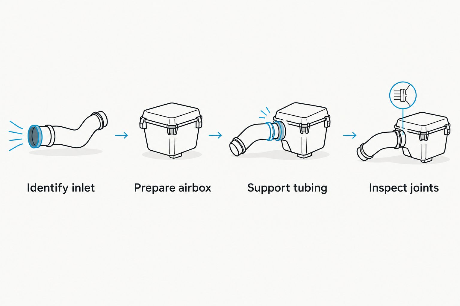
- Lay out the tubing in the order shown by the manufacturer. Identify orientation-sensitive bends and couplers before tightening anything.
- Assemble the route loosely, working 1 connection at a time. Seat each tube to the specified insertion depth rather than estimating an overlap.
- Check the entire run for kinked hose, flattened sections, sharp bends, and contact with hot or moving components. Follow the documented clearance requirements.
- Install the supplied brackets and supports at their specified locations. The airbox inlet must not carry the weight of an unsupported riser.
- Temporarily refit nearby body panels and check cargo-area access. A route that fits with panels removed still needs to fit after reassembly.
Expected result: The tube follows the intended route without pulling sideways on the airbox, collapsing at a bend, or interfering with the vehicle’s normal operation.
Secure the joints without crushing them
- Position each clamp on the clamping land specified by the fitting manufacturer. Keep it clear of the coupler edge and any position that would prevent even compression.
- Tighten clamps using the documented specification and method. Do not use extra torque to compensate for a mismatched coupler.
- Check that brackets support the assembly without forcing tubes out of alignment. Reposition the loose assembly before final tightening if necessary.
- Inspect adjacent wiring and hoses. Retain their original protection and routing unless the installation instructions specify otherwise.
Expected result: Each connection remains fully seated, the couplers are not visibly distorted, and the supported tube does not load the airbox fitting when lightly handled.
Final inspection and dry verification
Close the airbox and check the complete system
- Remove every temporary intake cover, tool, and loose fastener. Inspect the airbox interior before installing the correctly serviced filter.
- Seat the filter and lid according to the vehicle manual. Check the full sealing perimeter rather than relying on a latch closing.
- Confirm that all factory connections are retained or modified exactly as documented. Do not plug an unidentified port or drain to make the housing look sealed.
- Complete any manufacturer-specified leak-check procedure. Do not flood the airbox, block the intake while the engine runs, or apply improvised shop-air pressure.
- After any required sealant cure, start the vehicle outdoors with the system fully assembled. Keep clear of moving components and watch for warnings or abnormal operation.
- If the initial check is normal, follow the manufacturer’s dry operational-check procedure. Shut down and inspect for shifted tubing, rubbing, or disturbed clamps before returning to trail use.
Expected result: The assembled intake remains secure, the vehicle operates normally during the prescribed dry check, and no inspection item remains unresolved. Normal idle alone does not prove that the system excludes water.
Use 3 checkpoints in your 2026 installation record: the airbox connection, every tube joint, and the mounting supports. Photograph each after final assembly so you have a reference for later inspections.
Reconnecting the snorkel after filter service
You do not need a new routing plan every time you service the filter. You do need to restore the same verified connection without introducing dirt or leaving the tube under tension.
- Let the vehicle cool and clean around the service opening. Photograph any joint you must disconnect.
- Support the intake tube before loosening a connection. Do not let the riser hang from the remaining airbox fitting.
- Service the filter using the vehicle and filter manufacturer’s procedure. Inspect the lid seal and adapter while access is open.
- Reconnect the joint at its documented position and insertion depth. Replace damaged couplers, seals, or hardware with the specified parts.
- Repeat the final inspection before starting the engine. Do not assume that an untouched-looking clamp is correctly positioned.
Best for routine maintenance: Preserve the established routing and disturb only the connections needed for access. The drawback is that tight installations still require careful support during service; convenience does not justify bending the tube out of the way.
Troubleshooting
The coupler will not seat on the factory inlet
Check the adapter identification, orientation, and the condition of the mating surfaces. Remove dirt and inspect for an old seal left in place. Do not stretch, heat, or trim the coupler unless the manufacturer explicitly requires it. A persistent mismatch is a fitment problem to resolve before assembly.
The airbox lid no longer closes correctly
Check filter seating, trapped seals, misplaced hardware, and adapter interference. Loosen and realign the new connection if it is distorting the housing. Do not force the latches or shave the filter to create clearance.
The tube shifts or a joint starts separating
Check missing supports, insufficient insertion, incorrect clamp position, and routing tension. Reassemble the affected section to the kit instructions. Tightening a clamp harder does not fix a bracket pulling the joint apart.
The engine runs poorly after installation
Shut down and inspect for a forgotten protective cover, collapsed hose, disconnected sensor, or disturbed factory connection. Read diagnostic warnings using the service-manual procedure. Do not keep riding to see whether a restriction or warning clears itself.
You find moisture or dirt beyond the filter
Stop operating the vehicle and investigate the contamination path. Inspect the filter seal, airbox housing, and clean-side connections. If the engine stalled during water exposure or ingestion is suspected, do not restart or crank it; arrange recovery and follow the manufacturer’s inspection procedure.
Customize your workflow
Build your 2026 intake setup around serviceability, not just riser height. Keep the filter accessible, preserve the documented tubing route, and check that cargo cannot strike the assembly. Any later roof, rack, or bed accessory needs another clearance inspection.
R1 Industries carries aftermarket UTV accessories, but a different accessory does not validate snorkel fitment. Confirm each change against the actual vehicle and kit documentation. If you want additional dust-management equipment, verify that the manufacturers approve the combined intake arrangement rather than stacking components by hose diameter.
FAQ
Do I need to wire a snorkel intake tube into my factory airbox?
No. A snorkel intake tube connects mechanically through the specified fittings, couplers, seals, and clamps. Separate powered accessories have their own electrical instructions.
Where does a snorkel tube connect to the factory airbox?
The snorkel must feed the airbox’s unfiltered side at the connection specified for the kit. Do not connect it to the clean-side outlet or bypass the filter.
Can I use any hose that fits over the airbox inlet?
No. Diameter alone does not establish suitability for intake service, heat exposure, routing, or the required connection. Use the tubing and adapters specified by the kit manufacturer.
Should I seal every drain and opening in the airbox?
No. Modify only the drains and openings identified in the exact installation instructions. Blocking an unidentified connection can interfere with the factory system.
Does a snorkel let me cross deeper water in 2026?
A snorkel does not increase the vehicle manufacturer’s approved water-crossing limit. Other systems remain vulnerable, and a raised opening does not prove that lower intake connections exclude water.
Is the engine intake snorkel the same as a CVT snorkel?
No. The engine intake supplies combustion air through its filter, while CVT ducts move cooling air through the belt-drive housing. Trace each circuit separately and follow its specific instructions.
How do I test the connection without driving into water?
Use the snorkel manufacturer’s specified inspection and leak-check procedure. Visual checks and normal idle do not establish water protection; do not improvise a flooding or pressure test.
Can R1 Industries replace my vehicle-specific snorkel instructions?
No. R1 Industries is an aftermarket UTV parts retailer, and this guide provides a general installation sequence. Your vehicle manual and exact kit instructions determine the required fittings, routing, and checks.
One last thing
A clean-looking riser can hide a failed connection below it. Before your next 2026 ride, inspect the lowest joints and the airbox seal—not just the opening you can see above the bed. If a connection has shifted, resolve it before starting the engine.
