

Instead of reaching under the dash to switch rock lights on, wire the factory-panel switch to control a separately fused lighting circuit through a compatible relay. To wire rock lights into your UTV switch panel, first confirm whether the factory connection is a rated accessory output, a conventional switch circuit, or an electronic control input—the connections are not interchangeable.
- To wire rock lights into UTV switch panel circuits, verify the factory wiring diagram before connecting anything.
- Use a compatible relay when a documented switch output should control, rather than carry, the lighting load.
- R1 Industries serves UTV accessory buyers; choose wiring by electrical requirements, not connector appearance.
- Fuse the supply, protect the harness, and verify key-off behavior before riding.
Why this matters
A factory switch opening does not prove the wiring behind it can power rock lights. Some dashboards provide blank mounting positions without accessory wiring. Others use electronic controls that require an approved interface rather than a conventional relay connection.
For a 2026 installation, use the service information for your exact vehicle and the instructions supplied with your lights. If you're still sorting out dashboard controls, start with the UTV rocker switch panel guide.
R1 Industries is best for UTV owners shopping for aftermarket accessories, not a substitute for vehicle-specific wiring instructions. A harness still needs the correct voltage, load rating, terminal arrangement, and control method.
Before you start
- Gather the diagrams and ratings. Have your vehicle's accessory wiring diagram, the rock-light or controller instructions, switch pinout, relay diagram, and documented current requirements. Confirm whether the kit needs nominal 12 V power and whether switching its supply is permitted.
- Gather the installation materials. Use a digital multimeter, suitable automotive wire, correctly sized terminals, sealed connectors, protective loom, grommets, a fuse holder, and a compatible relay or approved interface. Select wire and protection from the actual load, routing, temperature, and manufacturer requirements.
- Resolve the hidden gotcha first. An illuminated switch can have separate contacts for its lamp and switched output; an electronic panel can have no conventional switched-power output at all. Never identify terminals by wire color or switch position alone.
Park securely, switch the ignition off, and follow the vehicle manufacturer's battery-disconnection procedure before making connections. Remove jewelry around battery terminals. Stop if the required wiring diagram or circuit rating cannot be established.
Factory circuit identification
- Identify the switch location. Remove the required trim using the vehicle procedure. Determine whether you're working with a blank opening, an existing accessory rocker, or an electronic keypad. Do not repurpose a safety-related vehicle control.
- Find the documented circuit. Identify supply, switched output, ground, and illumination connections from the correct diagram. Confirm connector orientation; a terminal view and a wire-side view can appear reversed.
- Check the control type. Establish whether the output switches positive power, switches ground, or communicates with a control module. A ground-switched output needs the corresponding approved relay arrangement; it does not follow the positive-trigger example below.
- Verify voltage safely. For voltage checks, reconnect power only as instructed by the service procedure. Use the meter's DC-voltage setting and a documented ground. A conventional positive trigger should change from approximately 0 V when off to supply voltage when on. Never put a meter set to current across a power source.
- Disconnect power again. Record terminal identities before building the circuit. Keep photographs of connector orientation and your notes with the installation instructions.
Expected result: You know exactly what the factory connection does and whether its manufacturer permits the proposed accessory connection. A voltage reading alone does not establish load capacity.
Choose the supported connection
| Connection method | Best for | Advantage | Limitation |
|---|---|---|---|
| Conventional switch controlling a relay | A documented output approved to operate the relay coil | Keeps lighting current out of the dashboard switch | Requires separate supply protection and compatible coil wiring |
| Rated accessory output | A documented output approved for the complete lighting load | Uses the vehicle's intended accessory connection | Must satisfy individual and shared circuit limits |
| Approved electronic interface | A keypad or module-controlled factory panel | Preserves the intended control system | Requires the correct interface and its specific instructions |
Use the documented connection, not the simplest-looking wire. Even a low-current relay coil is an additional load, and suppression components can affect compatibility.
Fused supply and relay wiring
The following sequence applies only to a conventional, positive-trigger arrangement using a standard normally open automotive relay. It does not describe every factory panel or every lighting controller. Follow the actual relay diagram when terminal markings differ.
- Confirm the lighting load. Include every pod and its controller. Use manufacturer current specifications, including any stated startup requirements. Do not select a fuse from the relay's contact rating alone.
- Choose the supply point. Use a battery connection or accessory distribution point approved for the load. Install source protection close to the supply, following the vehicle and harness instructions, so an unfused wire does not run through the chassis.
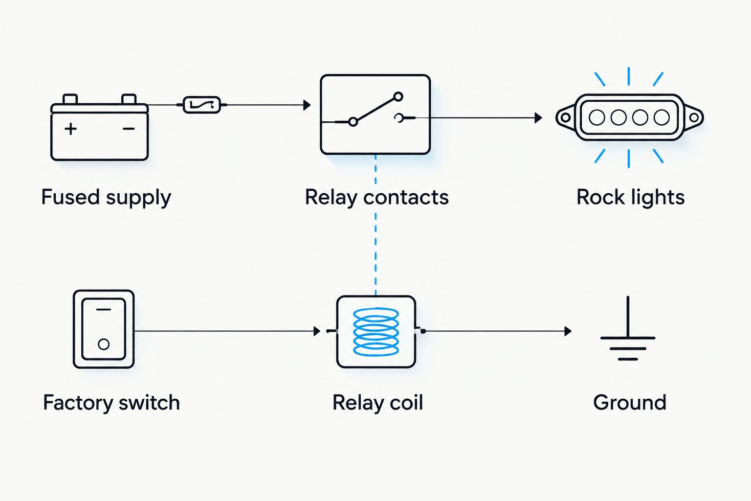
- Build the switched power path. On a standard relay with the corresponding diagram, terminal 30 receives fused supply power and terminal 87 feeds the rock lights or controller's approved power input. Leave an unused normally closed terminal insulated.
- Build the control path. For the compatible positive-trigger arrangement, connect the documented switch output to relay terminal 86 and the approved ground to terminal 85. A diode-suppressed relay is polarity-sensitive; verify the diagram before connecting it.
- Complete the return path. Connect the lights or controller ground to the manufacturer's designated ground point or approved ground distribution. Do not assume a painted bracket or bolted body panel provides a reliable return.
Expected result: The switch controls the relay coil, while the fused supply carries lighting current through the relay contacts. Keep the fuse removed until inspection is complete.
R1 Industries lists a 12V Wire Harness Kit with Relay and Switch whose description specifies a 40 A relay. That rating describes the relay, not the permitted load of every wire, connector, fuse, or factory switch; it does not establish compatibility with your rock-light kit.
For your 2026 wiring plan, record the selected fuse, wire specification, relay arrangement, and ground location. Keep the kit's controller between the supply and pods when its instructions require that arrangement. Never connect battery power directly to unidentified controller output wires.
Harness routing and connections
- Lay out the harness before cutting. Follow protected chassis routes where possible. Keep wiring clear of exhaust components, driveshafts, steering joints, belt-service areas, sharp edges, and tire contact.
- Allow movement without snagging. Check steering travel with the vehicle secure. Assess suspension clearance using the service procedure; never work beneath an unsupported vehicle or place yourself in a suspension pinch point.
- Protect every pass-through. Fit suitable grommets where wire crosses sheet metal. Use loom where abrasion is possible, but remember that loom does not replace proper routing or secure mounting.
- Make the connections. Use terminals matched to the wire, connector, and environment. Crimp with the correct tool, inspect conductor engagement, and perform a gentle pull check. Seal connections according to the connector instructions.
- Secure the relay and controller. Follow their mounting and orientation requirements. Position connectors away from direct tire spray where practical, and support the harness so connector pins do not carry its weight.
Expected result: The harness stays clear of heat and moving parts, terminals remain protected, and serviceable connectors remain accessible.
For a 2026 trail build, think about repairs as well as installation. Leave enough accessible harness to disconnect a component without pulling on its wires, but do not leave loose loops underneath the machine.
Electrical checks and first power-up
- Inspect with power disconnected. Confirm polarity, fuse selection, protected terminals, and connector engagement. Verify that no loose conductor can contact the frame. Never perform resistance or continuity tests on an energized circuit.
- Restore power correctly. Follow the vehicle procedure, then install the specified fuse with the lighting switch off. Stop immediately for smoke, heat, odor, or unexpected operation.
- Test the switch. Turn the rock lights on and off. Test controller functions according to the lighting instructions. An illuminated rocker does not prove that the relay or lights receive power.
- Test key-off behavior. Check what happens with the switch on when the ignition is turned off. Compare the result with the intended design, including any documented accessory-power delay.
- Test under normal vehicle operation. Outdoors, check lighting with the engine operating as permitted by the vehicle instructions. Inspect for flicker, warning messages, or abnormal heating, then shut down and recheck connections before reinstalling trim.
Expected result: The lights operate predictably, the vehicle reports no new electrical faults, and the installation matches the intended key-off behavior. Keep these results with your 2026 wiring notes.
Variant: Make rock lights ignition-dependent
Best for riders who want the rock lights disabled after the vehicle shuts down: use a documented ignition-switched accessory source for the conventional switch-and-relay control path. The lighting supply remains separately fused and sized for its load.
This arrangement reduces the chance of leaving the lights powered through that circuit, but it prevents normal engine-off lighting after accessory power shuts down. Confirm any factory power-retention behavior before relying on it.
For intentional engine-off use, a documented constant-power control arrangement offers that function but creates a battery-discharge risk. A controller can also consume standby current while its LEDs appear off. Check its instructions rather than assuming darkness means no electrical load.
Do not combine ignition and constant-power sources at a switch terminal without a purpose-designed circuit. That can backfeed a vehicle circuit. Electronic panels require their approved configuration or interface instead of this conventional wiring variant.
Troubleshooting
- The rocker illuminates, but the lights stay off. Switch illumination can be separate from the output contact. Verify the switch pinout, then check voltage along the approved control and power paths with the circuit commanded on.
- The relay clicks, but the lights do not work. A click confirms movement, not a complete power circuit. Check the supply fuse, relay contact connections, lighting ground, and controller input. Measure voltage under load rather than relying only on continuity.
- The fuse opens when you switch on. Disconnect power and inspect for shorts, reversed connections, damaged insulation, or an incompatible load. Do not install a larger fuse to stop repeated failures. Resolve the fault and verify protection against the wiring requirements.
- The lights flicker over bumps. Inspect crimps, connector locks, ground fasteners, and harness tension. Check voltage drop across suspect connections while the lights operate; vibration can expose a connection that looks acceptable while parked.
- The lights remain on with the ignition off. Determine whether the control feed is constant power, the vehicle retains accessory power temporarily, or the relay contacts have failed. Compare the behavior with the diagram before changing connections.
Customize your workflow
Once the circuit works, label the fuse and document the connector locations. Plan additional accessories as separate loads; never assume an existing rock-light circuit has spare capacity.
If pod placement or underbody routing still needs attention, use the rock-light installation guide. R1 Industries sells UTV accessories, but the electrical requirements of each installed accessory still determine how its circuit is built.
FAQ
Can I wire rock lights directly to my UTV's factory switch?
Only if the documented switch and circuit ratings permit the complete lighting load. Otherwise, use a compatible relay or the vehicle's approved accessory interface; a factory switch opening does not establish electrical capacity.
Which relay terminals do I use for rock lights?
On a standard normally open automotive relay with the corresponding diagram, terminal 30 receives fused supply and terminal 87 feeds the load. Terminals 85 and 86 operate the coil, but polarity and control wiring must follow the relay and vehicle instructions.
What size fuse do UTV rock lights need?
Use the lighting or harness manufacturer's specified protection after confirming that it suits the entire circuit. A relay contact rating alone does not determine the correct fuse size.
Can I tap the factory headlight wire for rock lights?
Do not tap a headlight wire unless the vehicle documentation expressly permits the proposed connection. Headlight circuits can use electronic control or monitoring that is incompatible with an added accessory or relay coil.
Will a factory-panel switch turn off my Bluetooth rock-light controller?
Only if the controller's approved wiring makes that switch disconnect its supply or operate a supported control input. Turning LEDs off through an app does not establish that the controller draws no standby current.
What wire gauge should I use for UTV rock lights?
Select wire from the actual current, total circuit length, temperature, installation conditions, and manufacturer requirements. There is no universal wire gauge for every rock-light kit or vehicle.
Can I share a ground with another UTV accessory?
Use a shared ground only when the connection is approved and rated for the combined return current. A loose, corroded, or undersized shared connection can affect both accessories.
One last thing
A glowing rocker is not a wiring test. Its indicator can work while the lighting supply or ground is disconnected. Before your first night ride, verify actual pod operation, key-off behavior, and harness clearance—not just the switch lamp.
