

Instead of reaching for a separate lamp every time you need cab light, wire your dome lights through a documented, load-rated factory switch circuit or a compatible relay harness. This guide shows you how to identify the circuit, protect the wiring, and test the installation without treating an empty dash opening as a powered accessory connection.
- To wire dome lights into utv switch panel circuits, verify the factory wiring diagram before connecting power.
- Use direct switching only when the complete circuit supports the dome-light load.
- Use a compatible relay harness when the dash switch should control power rather than carry the lighting load.
- R1 Industries Offroad suits UTV owners shopping aftermarket accessories; wiring compatibility still requires vehicle-specific documentation.
Why this matters
A factory switch panel can mean a row of empty switch blanks, conventional wired switches, or an electronic control system. Those arrangements require different connections. A switch that fits the opening does not prove electrical compatibility.
Start with the circuit, not the rocker shape. The UTV rocker switch panel guide covers accessory-control choices; the steps here focus on connecting cab lighting safely.
For a 2026 wiring project, use documentation matching your actual vehicle year, model, and installed equipment. A current accessory listing does not replace that wiring diagram.
Before you start
- Gather the documentation. Have the vehicle wiring diagram, dome-light instructions, switch terminal diagram, and any relay-harness instructions. Identify supply voltage, light current, circuit capacity, polarity, and whether the factory output switches positive or ground.
- Gather the materials. Use a multimeter, suitable crimping tools, automotive-rated wire, sealed connectors, loom, grommets, mounting hardware, and the specified fuse protection. Match wire size to current, total circuit length, installation conditions, and the accessory instructions.
- Check the hidden gotcha. An illuminated rocker can have separate terminals for its backlight and switched output. Electronic factory controls can also use signal wiring rather than a usable accessory-power output. Never connect a lamp or relay coil to an unidentified terminal.
This guide describes a conventional switched-positive installation on a confirmed 12 V DC accessory system. It is not a pinout for every Polaris RZR, Can-Am Maverick, Kawasaki KRX, or other UTV. If the diagram shows module-controlled switching, ground switching, or a proprietary accessory interface, use the approved interface instructions or an experienced installer.
Choose your circuit layout
Decide how the panel will control the dome lights before removing trim. These are circuit options, not interchangeable installation shortcuts.
| Circuit option | Best for | Advantage | Limitation |
|---|---|---|---|
| Direct switching | A documented accessory circuit and switch rated for the complete lighting load | Fewer components and connections | The factory feed, switch, terminals, and wiring all carry lamp current |
| Relay switching | A documented, compatible control output with a separate protected lighting feed | Keeps lamp current out of the dash control circuit | Adds a relay, connections, and compatibility checks |
Use direct switching only when every part of the circuit supports the load. Choose relay switching when the documented control arrangement requires separating lamp power from switch control. A relay does not create spare capacity in the charging system or make an unsuitable factory output safe.
R1 Industries Offroad sells aftermarket UTV accessories, but the retailer name does not establish a vehicle pinout. Match the light, harness, and vehicle documentation before making connections.
Factory circuit identification
Identify the feed, output, and ground
- Park securely, switch the ignition off, and expose the panel using the vehicle's trim-removal procedure. Photograph existing connectors before unplugging anything. Keep the dome lights disconnected while identifying the circuit.
- Locate the documented accessory feed, switched output, ground, and illumination connections. Record connector identifiers and cavity positions from the diagram. Do not substitute wire color for a verified terminal identity.
- Where the service procedure permits energized testing, set the meter to DC voltage and confirm lead placement. Keep the red lead out of the current-measurement socket for voltage checks. Probe accessible test points without spreading terminals or damaging connector seals.
- Check the documented feed with the key off and on. For a conventional switched-positive output, check switch-off and switch-on behavior against the diagram. Disconnect battery power using the vehicle procedure before cutting, crimping, or changing connections.
Expected result: You have identified a supported power source, control output, and return path, with the intended key behavior confirmed. An unexplained voltage reading is a reason to stop, not permission to splice.
Never use resistance or continuity mode on an energized circuit. If the manual requires a breakout lead or diagnostic procedure, follow it rather than piercing factory insulation.
Protected lighting feed
Build the power path before connecting the panel
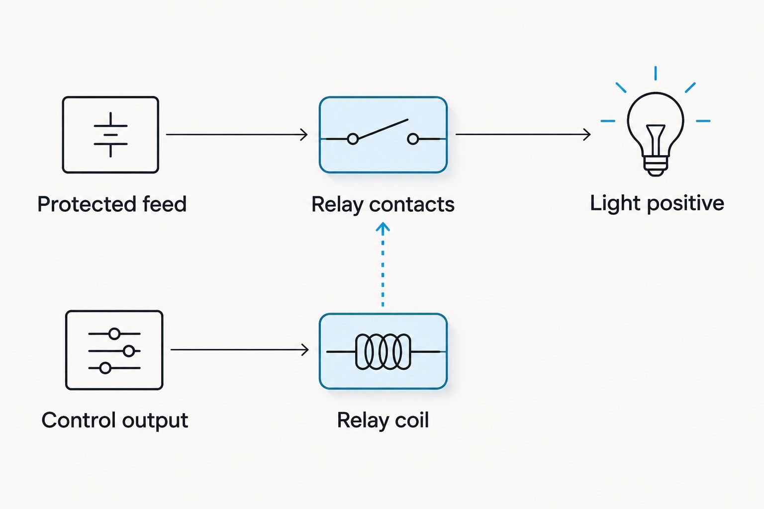
- Choose the layout. For direct switching, route the approved protected accessory feed through the correctly rated switch to light positive. For relay switching, route the protected lighting feed through the relay's normally open power contacts to light positive.
- Protect the feed. Install the specified fuse near the supply connection so the added wire is protected from its source. Select protection for the complete circuit, including its smallest conductor and lowest-rated component. Follow accessory requirements for startup current.
- Connect the return. Run light negative to the documented ground bus or approved grounding point. Do not assume a roof bracket, painted cage clamp, or hinge provides a reliable return path.
Expected result: The lamp-power circuit has an identified supply, appropriate overcurrent protection, and a documented ground. Keep the added fuse removed until the installation is ready for testing.
The relay layout separates the lighting load from the control signal. The switch still needs a compatible connection; it is not automatically safe to attach a relay coil to any factory output.
Confirm component ratings
A 12 V relay coil belongs on a compatible nominal-voltage control circuit; a 24 V coil is not an interchangeable substitute. Voltage is only part of the check: contact rating, coil current, suppression, environmental protection, and terminal arrangement also matter.
A relay with internal diode suppression requires correct coil polarity. Follow its printed diagram and harness instructions rather than a generic internet pin map. Likewise, a large relay contact rating does not establish the safe capacity of the harness wire or its fuse.
For your 2026 installation record, write down the actual fuse specification and wire size you install. Keep that record with the vehicle documents rather than relying on memory during a trailside repair.
Switch connection and roof routing
Connect control and secure the harness
- Connect the control circuit. With battery power disconnected, connect the verified switch output to the documented relay-control connection, or complete the approved direct-switch circuit. Wire rocker illumination separately according to its diagram. Never join backlight and load terminals just because both illuminate something.
- Route the roof harness. Follow a protected path away from exhaust heat, sharp edges, steering parts, seat tracks, belts, and occupant contact. Use grommets at panel penetrations and support the harness without crushing its insulation. Do not drill structural cage tubing for wire routing.
- Provide a service disconnect. If the roof is removable, position a sealed connector where you can reach it before lifting the roof. Add enough slack for service without leaving loose loops near occupants or moving parts.
- Finish the terminations. Use connectors and crimps matched to the conductor size. Inspect each termination, perform the connector manufacturer's retention check, and protect exposed wiring. Keep electrical tape from becoming the only support or weather barrier.
Expected result: The dome-light wiring stays clear of movement, the roof can be serviced, and the switch controls only its intended circuit.
Aim the lamp before final tightening. You need light on buckles, controls, and stored gear, not glare reflected in the windshield. R1 Industries Offroad UTV accessories should be evaluated against the actual mounting space and electrical requirements, not just appearance.
Power-up and verification
Test before reinstalling trim
- Inspect the complete installation with power isolated. Confirm polarity, covered terminals, secure grounds, and correct connections. Remove tools from the battery area, then restore battery connections using the vehicle procedure.
- With the light switch off, install the specified fuse and test the intended key states. On the conventional switched-positive circuit described here, the light feed should be approximately 0 V relative to its verified ground when fully disconnected by the switch or relay. Unexpected readings require diagnosis against the diagram.
- Switch the dome lights on and check operation under load. Measure voltage at the supply and across the lamp terminals if the light is dim or unstable. Check the positive and ground sides separately for unwanted voltage drop.
- Turn the lights off, check other vehicle functions, and inspect for hot connections, odor, flicker, or fuse failure. Stop immediately if any appear. Refit trim only after wiring remains clear and operation matches the intended key behavior.
Expected result: The dome lights respond correctly, factory functions remain unchanged, and no fault appears during the stationary test.
Never increase fuse size to make a fault disappear. A blown fuse calls for diagnosis of the wiring, load, and protection requirements.
Second variant: dome lights with the key off
Key-controlled lighting helps prevent leaving the dome lights on after parking. Key-off lighting is useful while loading gear or checking the cab at camp, but it creates a battery-drain risk.
For key-off operation, use a documented constant-power lighting feed with suitable protection and a dedicated control arrangement. In a relay circuit, changing only the lamp feed does not enable key-off operation if the relay coil still receives power exclusively with the key on.
Do not bridge constant power into the factory ignition-switched feed. That can backfeed circuits intended to shut down. Use an approved isolated arrangement instead.
For a 2026 camping setup, decide which behavior you need before building the harness. Automatic door operation is a separate project: use a compatible controller or documented door-input interface rather than connecting directly to an unidentified factory door-signal wire.
Troubleshooting
- The rocker lights up, but the dome light stays dark. Check the actual switched output, lamp polarity, fuse, and ground. An illuminated switch face does not prove its load terminal has power.
- The relay clicks, but the lamp does not illuminate. Verify the protected supply at the relay power input and output under command. A clicking coil does not prove the contacts or lamp ground are connected correctly.
- The dome light flickers over bumps. Isolate power and inspect crimps, connector retention, grounds, and pinch points. Do not keep riding with an intermittent connection hidden behind the trim.
- The fuse opens when the switch turns on. Disconnect power and check for reversed connections, damaged insulation, incorrect relay wiring, or excessive load. Replace the fuse only after correcting the cause.
- The light glows faintly when switched off. Check for an illumination-terminal mix-up, controller leakage, or an unintended return path. Do not add a resistor or bridge terminals without a documented remedy.
Customize your workflow
Label the added circuit, photograph the finished routing, and keep the component diagrams with your 2026 service notes. A future roof removal or dash repair should not require rediscovering every connection.
Before adding more accessories, reassess the feed capacity and charging-system load. A working dome-light circuit is not proof that the same branch can support whips, a sound bar, or other lighting. Keep separately controlled accessories on appropriately designed branches.
FAQ
Can I wire dome lights directly to my UTV's factory switch?
Yes, but only when the documented factory feed, switch, connectors, and wiring support the complete lighting load. Otherwise, use a compatible protected relay circuit or approved accessory interface.
Do UTV dome lights always need a relay?
No. A documented, appropriately rated direct-switch circuit can power suitable dome lights; a relay separates lamp current from the control circuit when the installation requires it.
Which wire on the factory switch powers the dome light?
Use the switched-output terminal identified in the exact vehicle and switch diagrams. Wire color and rocker position do not establish terminal function.
What fuse size should I use for UTV dome lights?
Use the protection specified for the lights and harness while keeping it within every conductor and component rating. There is no universal dome-light fuse size.
Can my dome lights work with the ignition off?
Yes, with a documented constant-power feed and a control arrangement designed for key-off operation. Do not bridge constant power into an ignition-switched factory circuit.
Can I ground a dome light to the roll cage?
Use the vehicle's approved grounding point or ground bus instead of assuming the cage provides a reliable return. Paint and bolted joints can interrupt electrical continuity.
Does this guide apply to every 2026 UTV switch panel?
No. Switch blanks, conventional switches, and electronic accessory controls need different connections, so verify the exact vehicle diagram before installing the lights.
One last thing
Make the roof connector accessible before you need to remove the roof. A clean-looking installation becomes a service problem when its wiring traps the panel overhead. Finish the job by showing anyone who services the UTV where that connector and the added fuse are located.
