

Instead of remembering to switch off your UTV whip lights after every ride, use a verified ignition-switched signal to control their power through a suitable relay. This shuts the lights off with the key; shutting them off whenever the engine stops—even with the key on—requires a separate, vehicle-approved engine-running signal.
- To automatically shut off UTV whip lights, ignition control handles key-off; engine-stop control requires an engine-running signal.
- Use a verified accessory signal to trigger a relay, not an unidentified ignition or ECU wire.
- Switch the controller’s power feed when its instructions permit, so remote-off does not leave it powered.
- R1 Industries serves UTV owners shopping aftermarket parts and accessories; verify wiring requirements before changing a lighting harness.
Why this matters
Key off and engine stopped are different electrical conditions. A stalled engine can leave an ignition-switched accessory circuit energized. So can parking with the key on while you check the dash.
For a 2026 lighting project, decide which shutdown event you actually need before choosing hardware. A key-off relay solves forgotten lights after you remove the key. It does not prove that the engine is running.
R1 Industries is best for UTV owners shopping aftermarket parts and accessories. Start with the lighting equipment you already have, rather than replacing working whips to change their shutdown behavior. The R1 Industries catalog is a shopping reference, not a substitute for your vehicle’s wiring diagram.
Before you start
- Get the correct documentation. Have the vehicle service wiring diagram, whip-controller instructions, and the diagram for any existing harness or switch panel. Match the exact vehicle configuration, including a 2026 model where applicable.
- Gather suitable materials. Use a digital multimeter, automotive-rated relay or approved accessory-control module, correctly sized wire, circuit protection, sealed connectors, and proper crimping tools. Select ratings from the lighting load, wire run, and manufacturer instructions—not a generic fuse recommendation.
- Check the hidden gotcha. An accessory terminal can remain live after key-off, and a remote can turn LEDs dark without disconnecting controller power. Identify both the actual switched source and every controller power feed before altering anything.
Park securely, keep the transmission in the manufacturer-specified parked condition, and follow the service procedure for battery isolation. Never use resistance or continuity mode on an energized circuit. If the documentation does not identify an approved accessory connection, have a qualified installer identify it before proceeding.
Choose the shutdown behavior
Both workflows remove a manual shutdown task, but they respond to different events. Best for most riders: key-off control, provided turning the key off is part of parking the machine.
| Workflow | Best for | Advantage | Limitation |
|---|---|---|---|
| Ignition-switched relay | Riders who want whips off when the key is off | Uses a documented switched accessory source to control a separate lighting feed | Lights can stay powered with the engine stopped and key on |
| Engine-running control | Riders who specifically require shutdown after a stall or engine stop | Responds to an approved engine-running signal rather than key position alone | Requires vehicle-specific signal compatibility and control hardware |
A manual rocker switch still earns its place. With the correct arrangement, you can turn the whips off while driving, while automatic control prevents them staying powered after the selected shutdown event.
Do not assume a harness advertised as plug-and-play already provides ignition shutdown. Connector convenience and automatic power control are separate features. Verify the wiring diagram for any R1 Industries UTV whip-light setup before changing its power connections.
Ignition signal verification
The trigger tells the relay when to close; it should not carry the whip-light load. On a nominal 12 V vehicle system, distinguish battery voltage from 0 V at the intended trigger point, using the service manual’s operating conditions and tolerances.
- Locate the approved accessory source. Find the connection identified for switched accessories in the vehicle documentation. Do not select a wire by color alone or probe an unidentified ECU connector.
- Measure with the key off. Set the meter to DC voltage, following its instructions, and measure between the approved source and specified ground. A source intended for immediate key-off shutdown should settle to approximately 0 V after any documented shutdown delay.
- Measure with the key on. Confirm that the source becomes energized in the intended operating position. Check whether the accessory position also energizes it.
- Check starting behavior. With the machine safely prepared for starting, record whether the source drops out during cranking. This determines whether the whip controller will lose power during a restart.
- Confirm trigger capacity. Verify that the accessory output can operate the selected relay coil or module input. Use an approved interface where the vehicle requires one.
Expected result: You have a documented source that changes state with the key and can safely operate the selected control input. Label it before disconnecting the battery for installation.
For a 2026 machine with electronic accessory management, follow its documented connection procedure. A voltage reading alone does not establish that a circuit is suitable for an added load.
Relay and controller power path
Keep the lighting power path separate from the trigger path. The battery or approved distribution point supplies the lighting circuit through correctly selected protection; the switched signal operates the relay control circuit.
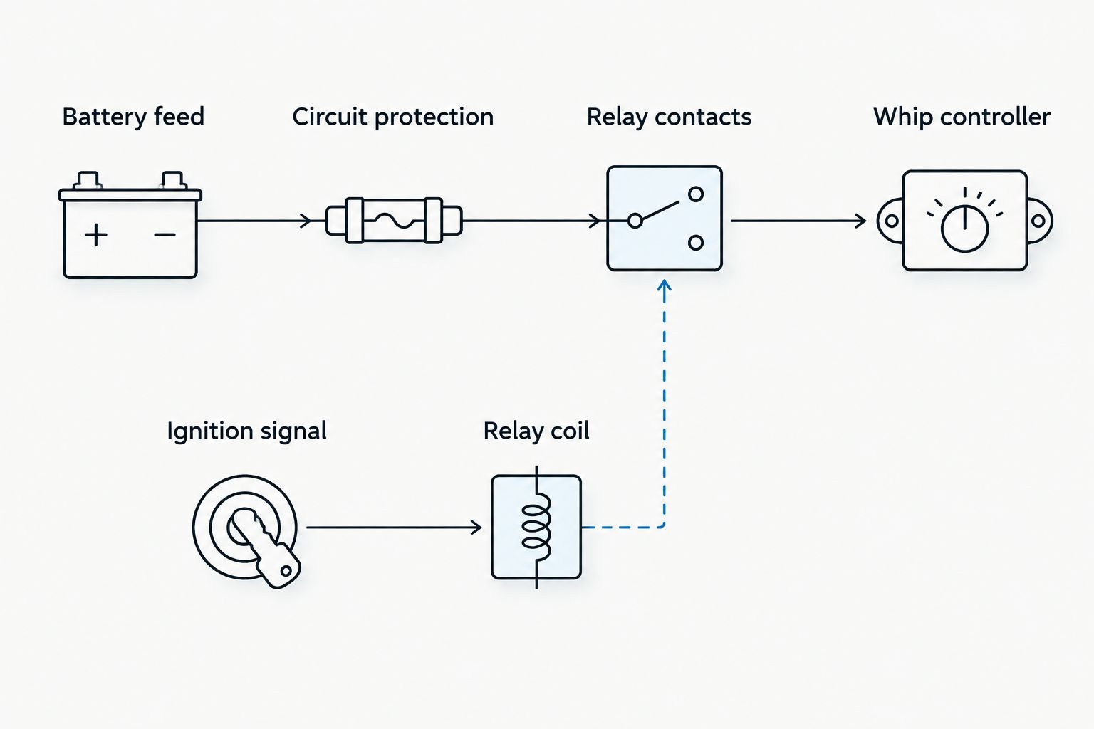
Treat this layout as the circuit concept, not a vehicle-specific pinout. Your relay diagram, harness instructions, and vehicle documentation determine the actual connections.
- Identify the controller supply. Trace the positive power input and ground using the whip manufacturer’s diagram. Determine whether the controller has additional constant-power, switch, or signal connections.
- Isolate power. Turn the vehicle off and follow the manufacturer’s battery-disconnection procedure. Confirm that the circuit is de-energized before cutting, crimping, or moving terminals.
- Connect the protected supply. Route the approved power source through circuit protection to the relay’s common contact. Position protection near the supply as specified for the installation, so the upstream wire is not left unnecessarily unprotected.
- Connect the switched output. Connect the normally open contact to the controller supply only where the controller instructions permit power switching. Preserve required inline protection.
- Connect the control circuit. Wire the approved ignition source, optional rocker switch, and relay coil according to their diagrams. Observe polarity on relays with internal suppression diodes.
- Secure the harness. Use suitable sealed connections and abrasion protection. Keep wiring away from exhaust heat, sharp edges, suspension travel, and pinch points; provide strain relief at connectors.
Expected result: The controller receives power only when the relay closes, and the lighting load does not pass through an inadequately rated accessory trigger.
Common automotive relay markings include 30 for common, 87 for normally open, and 85/86 for the coil. Verify the diagram printed on the actual relay; do not infer terminal positions from another relay’s appearance. On a changeover relay, 87a is normally closed and is not interchangeable with 87.
Shutdown and restart checks
Do not close the dash until the installation passes a complete operating check. Your 2026 installation record should show what happens at key-off, during starting, and after a restart—not just whether the whips light up.
- Inspect before energizing. Check polarity, secure connections, circuit protection, unused-terminal insulation, and harness clearance. Reconnect power using the vehicle procedure.
- Test key-on operation. Enable the rocker switch, if fitted, and turn the key to the intended operating position. Confirm that the relay closes and the controller receives power.
- Test key-off shutdown. Turn the key off with the rocker still enabled. Confirm that the lights extinguish and the controller supply falls to approximately 0 V after any documented delay.
- Test restart behavior. Cycle power and restart the vehicle safely. Confirm whether the controller restores its previous setting or requires a command; use that observed behavior when deciding whether the arrangement meets your needs.
- Test manual control. Confirm that the rocker disables the lights as intended. Check that its indicator does not create an unintended alternate power path.
- Check the finished installation. Look for warning messages, flicker, loose connections, or abnormal heating. Shut down immediately if a fuse opens, insulation heats, or wiring smells hot.
Expected result: Key-off removes controller power, key-on restores the intended operation, and the vehicle shows no new electrical faults.
If you are integrating an existing dashboard switch, the guide to wiring LED whip lights into a factory switch panel covers the adjacent installation topic. Keep the vehicle-specific circuit ratings in charge of the final design.
Shut the whips off whenever the engine stops
Best for actual engine-stop shutdown: an approved engine-running control system. An ignition relay alone cannot distinguish a running engine from a stalled engine with the key still on.
Use a vehicle-documented engine-running output with a compatible interface or accessory controller. Confirm signal type, input requirements, shutdown behavior, and starting behavior before connecting it. A logic input and a relay coil are not interchangeable loads.
Do not tap an injector, ignition coil, crank sensor, or communications wire to create a running signal. Those circuits are not general accessory outputs.
A voltage-sensing controller uses system voltage as a proxy; it does not directly measure engine operation. Battery condition, charging behavior, and accessory loads affect that relationship. Choose it only where the manufacturer explicitly supports the vehicle and the required behavior.
For a 2026 engine-running installation, include a controlled engine-stop check with the key remaining on, performed under the vehicle manufacturer’s safe operating procedure. The controller must remove whip power under that condition to meet the article’s engine-stop goal.
Troubleshooting
The whips stay on after key-off
Measure the relay trigger and controller supply separately. If the trigger remains energized, check for retained accessory power or an incorrect source; if the trigger is off but the supply remains live, inspect the selected contacts, an alternate feed, or welded relay contacts.
The whips shut off during cranking
Check whether the accessory trigger drops out during starting. That behavior can be intentional; use an approved alternative source or compatible control module if uninterrupted operation is required, rather than bypassing the shutdown circuit.
The relay clicks, but the whips stay dark
A click confirms movement, not a complete power circuit. Check the protected supply, normally open output, controller ground, and connector polarity; compare voltage at the controller with voltage at the source under load.
The fuse opens or a connection gets hot
Disconnect the circuit and inspect for shorts, damaged insulation, incorrect wiring, poor crimps, and unsuitable component ratings. Never install a larger fuse simply to stop repeated failures. Find the fault and verify the conductor protection first.
The whips reset after every shutdown
Check the controller’s documented power-loss behavior. Removing its supply can reset settings; use a manufacturer-approved enable input only if it provides the behavior you need, and recognize that leaving controller power connected is not complete electrical shutdown.
Customize your workflow
Add other accessories only after the whip circuit passes its checks. Separate branch protection and independently rated outputs make faults easier to isolate; an ignition trigger is not permission to put every accessory load on one wire.
For R1 Industries UTV accessory projects, retain the wiring diagrams and label the new circuit. Record the fuse specification, wire selection, source connection, and shutdown behavior in your 2026 maintenance notes so later upgrades do not bypass the protection.
FAQ
How do I automatically shut off UTV whip lights with the ignition?
Use a verified ignition-switched accessory signal to operate a suitable relay that switches the whip-controller power feed. Follow the vehicle, relay, and lighting instructions for circuit protection, ratings, and connections.
Will ignition-controlled whip lights turn off if my engine stalls?
Not necessarily: ignition-controlled whip lights follow the selected ignition circuit, not engine rotation. Actual engine-stop shutdown requires an approved engine-running signal and compatible control hardware.
Can I connect my whip lights straight to a switched accessory terminal?
Only if the vehicle and lighting instructions permit the complete load on that terminal. Otherwise, use the approved accessory output as a relay trigger and supply the lighting through a separately protected power circuit.
Does turning whip lights off with the remote disconnect the controller?
A remote-off command does not establish that controller power is disconnected. Check the controller diagram and measure its supply to distinguish dark LEDs from an electrically isolated controller.
What size fuse should I use for UTV whip lights?
Use the fuse specification required by the lighting harness and the installed circuit design. Fuse selection must protect the conductors and account for component ratings; there is no universal fuse size for every whip setup.
Can I keep my rocker switch with automatic shutdown?
Yes, when the wiring design places the rocker within the approved control arrangement. Verify the switch contacts and indicator wiring so neither bypasses automatic shutdown nor creates an unintended power path.
Why do my whip lights forget their color after key-off?
The controller can lose its selected settings when its power supply is removed, depending on its design. Check its documented memory behavior before choosing between full supply switching and a supported enable input.
One last thing
Test with the rocker left on. If automatic shutdown only works after you remember to switch the rocker off, the installation has not removed the manual task. Then check the engine-stopped, key-on condition separately: that is the test that distinguishes ignition shutdown from engine-running control.
